

Supporting EV Projects Since 2009!
Founded on a passion for sustainable mobility and a greener future, Evolve Electrics has swiftly become a go-to destination for electric vehicle enthusiasts and professionals alike. As a leading distributor of top-tier electric vehicle parts, we pride ourselves on offering a diverse and high-quality inventory that caters to budding EV hobbyists, academic institutions, and professional industry experts.
But our services go beyond just distribution. Our team, armed with extensive knowledge and experience in the electric vehicle domain, also offers invaluable consultation services, guiding clients through every step of their EV journey. At Evolve Electrics, we're not just about parts; we're about driving the future, one electric mile at a time.
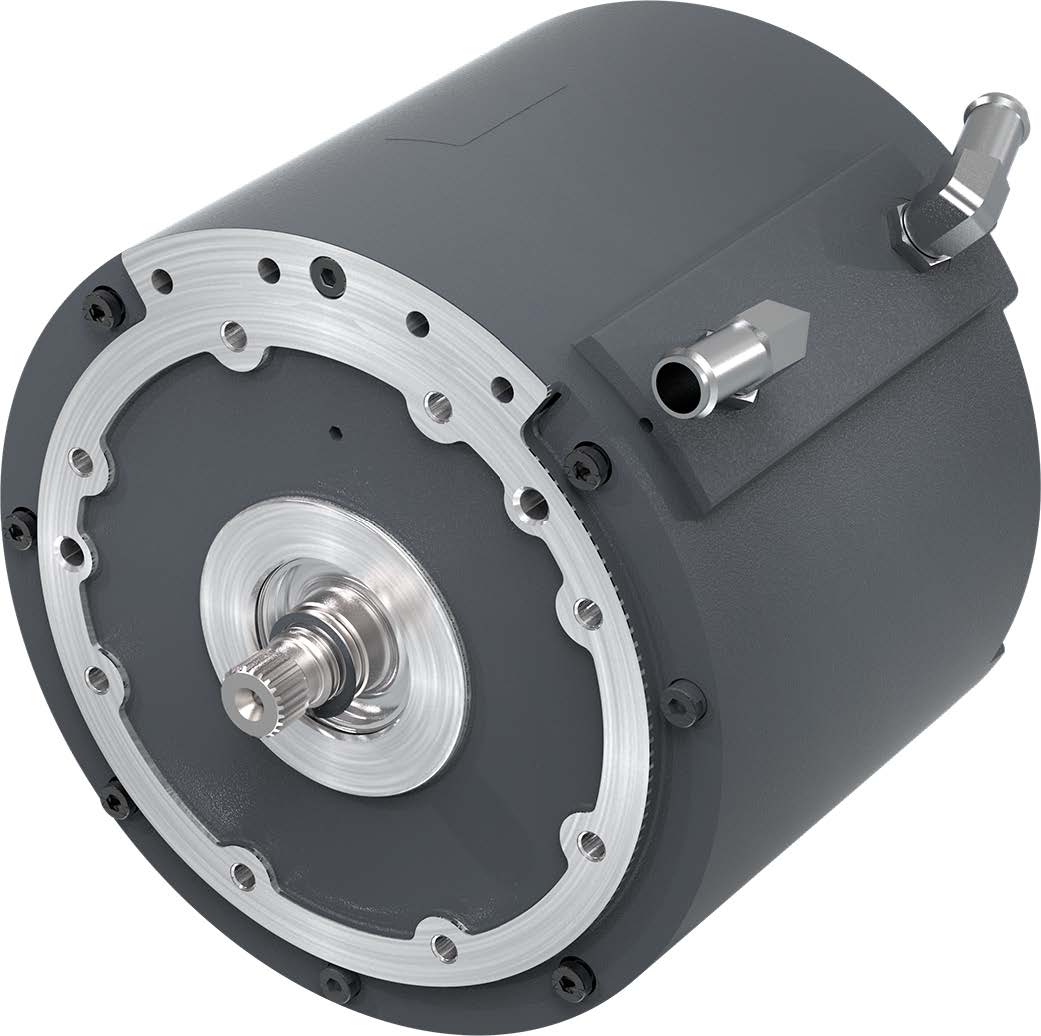
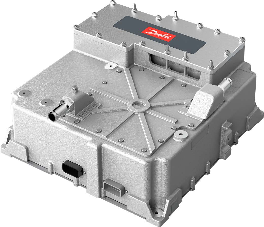
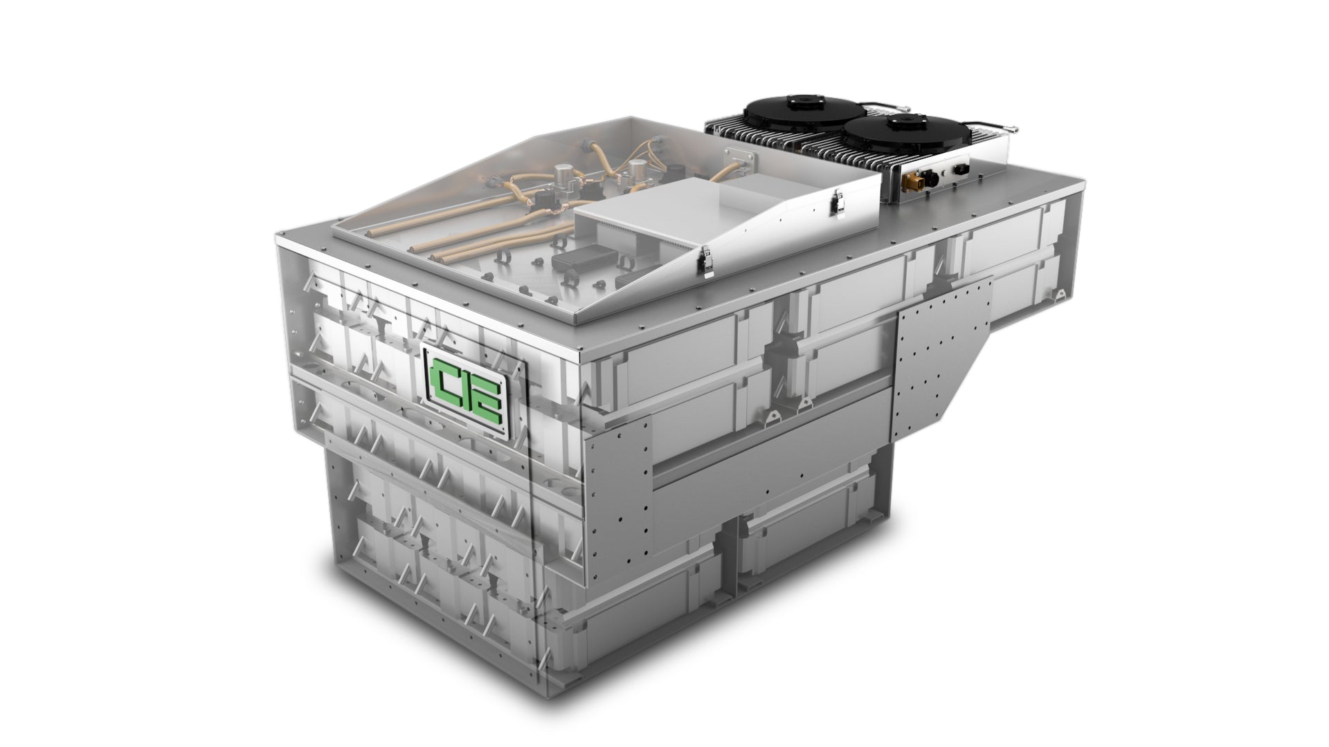
Danfoss EM-PMI250 Motor & EC-C1200D Inverter
General System Outline
See how it all comes together
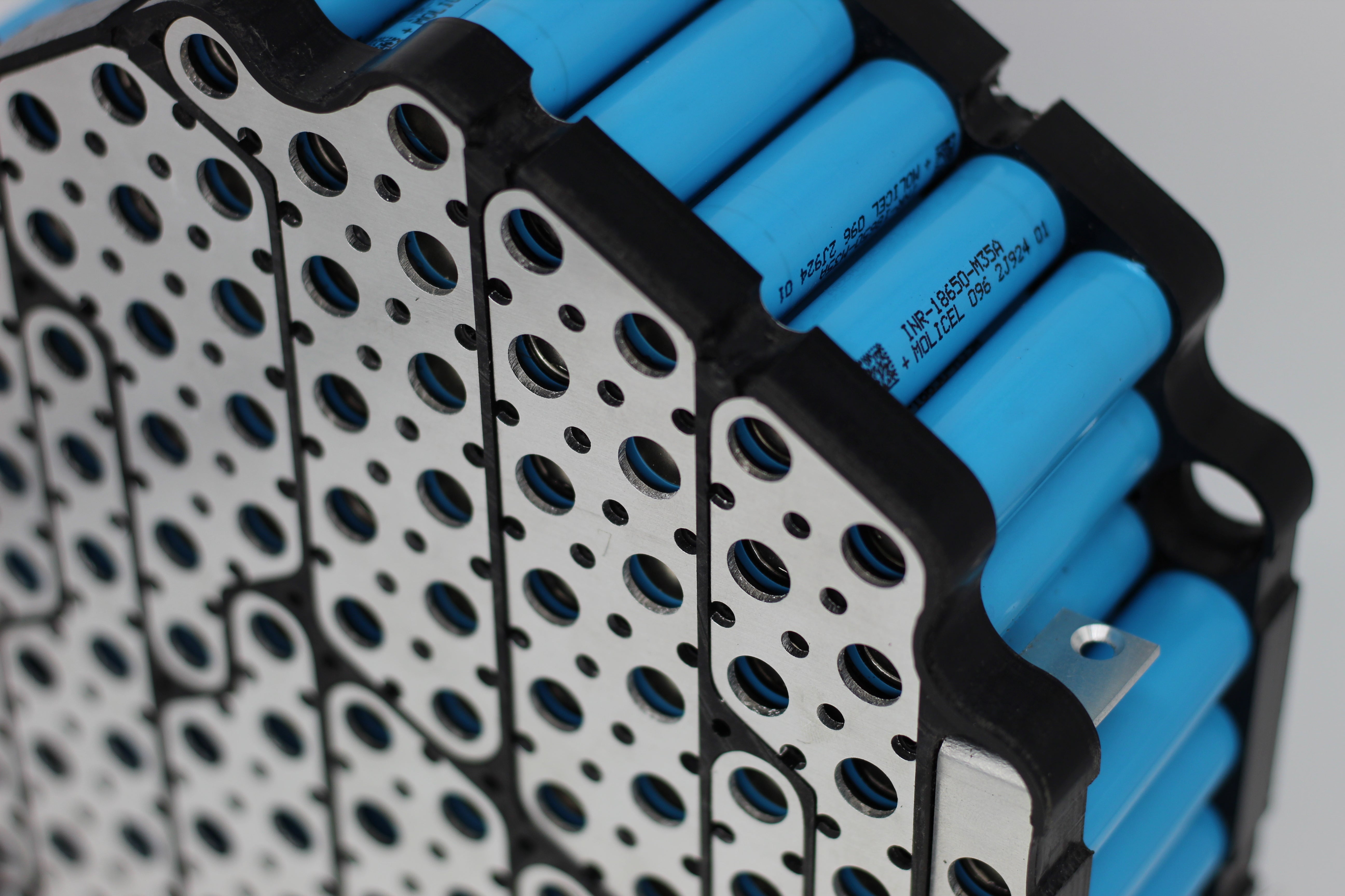
![[Chargers] - EVolve Electrics](http://evolveelectrics.com/cdn/shop/products/tesla-model-s-lithium-ion-18650-ev-module-22-8-volt-5-3-kwh.jpg?v=1578519425&width=600)
![[Chargers] - EVolve Electrics](http://evolveelectrics.com/cdn/shop/products/A9RD6BD.png?v=1602761324&width=1227)

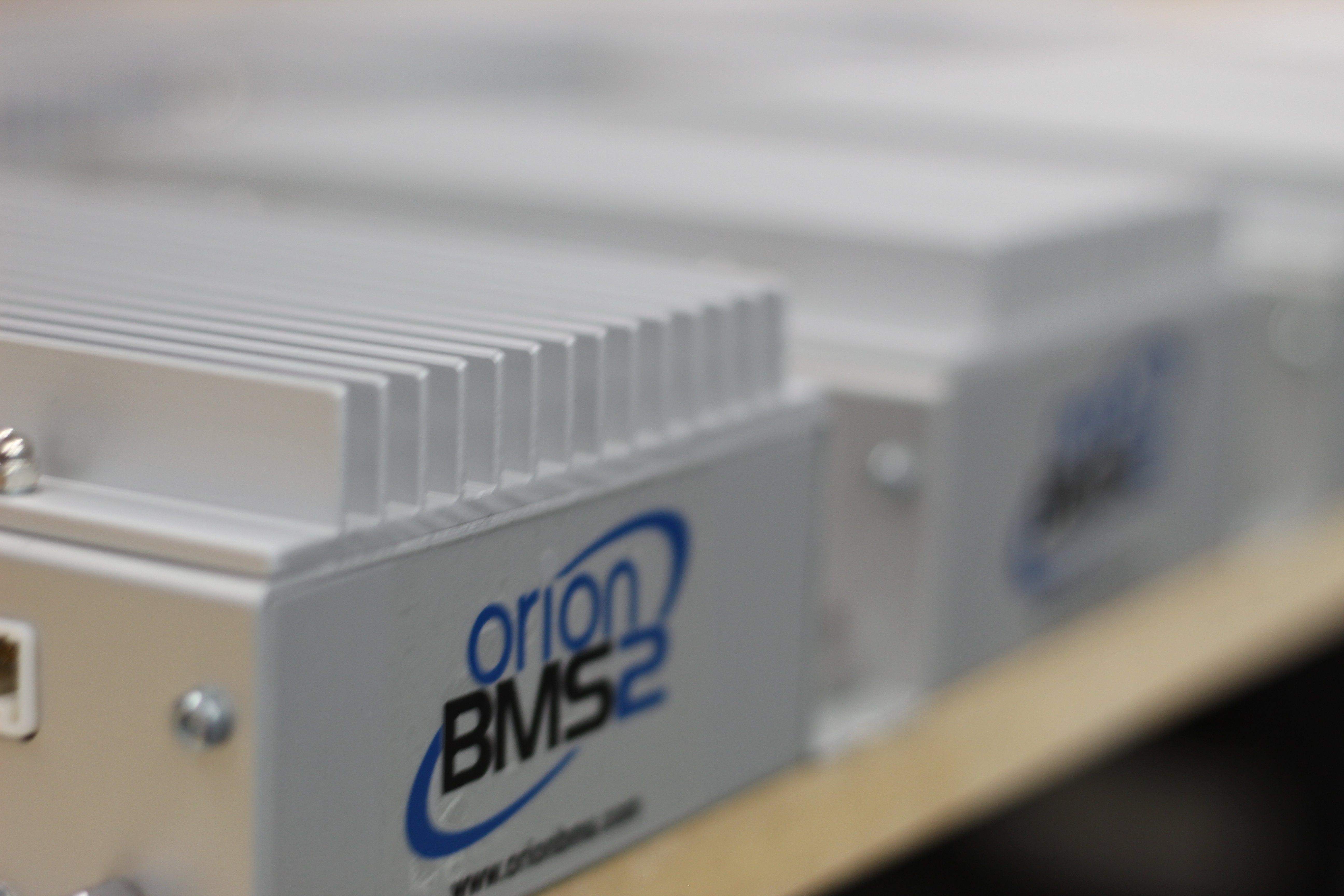
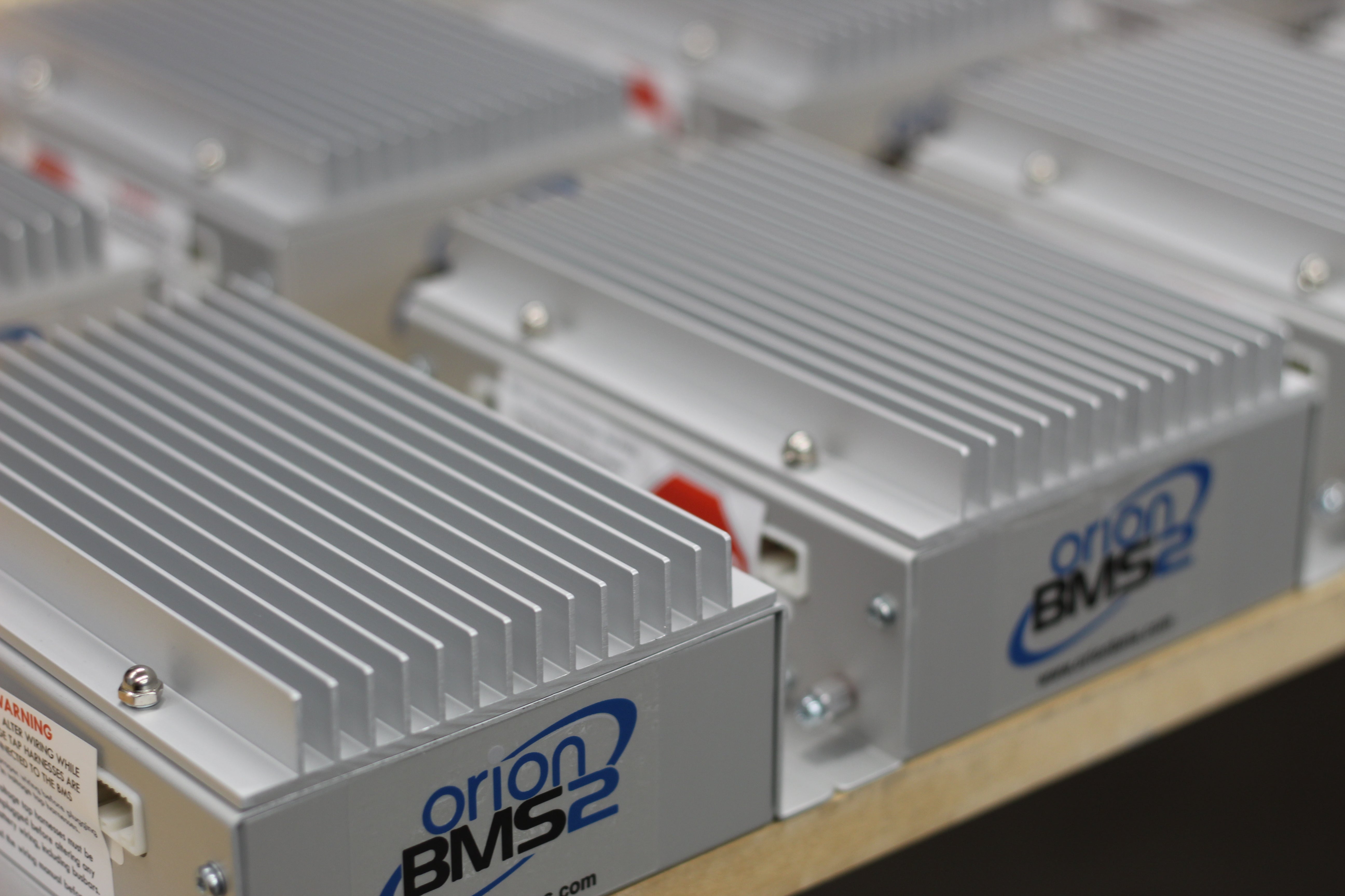
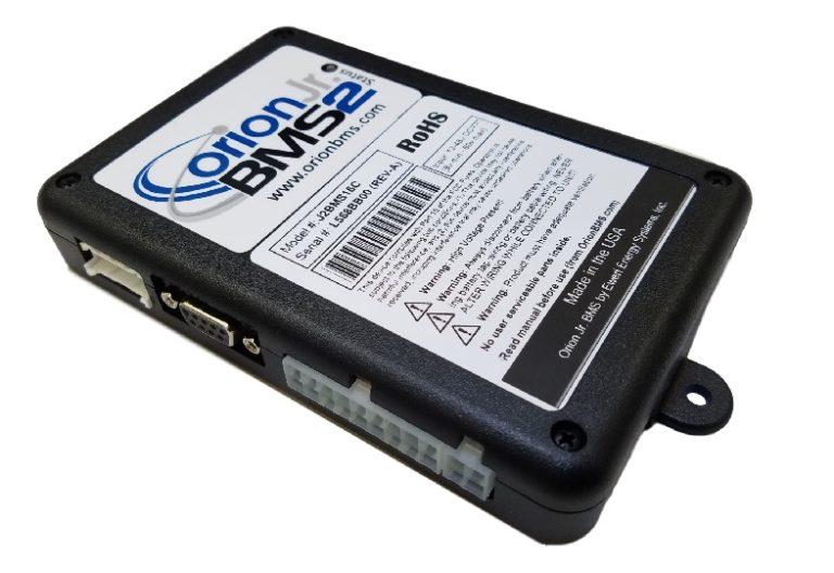
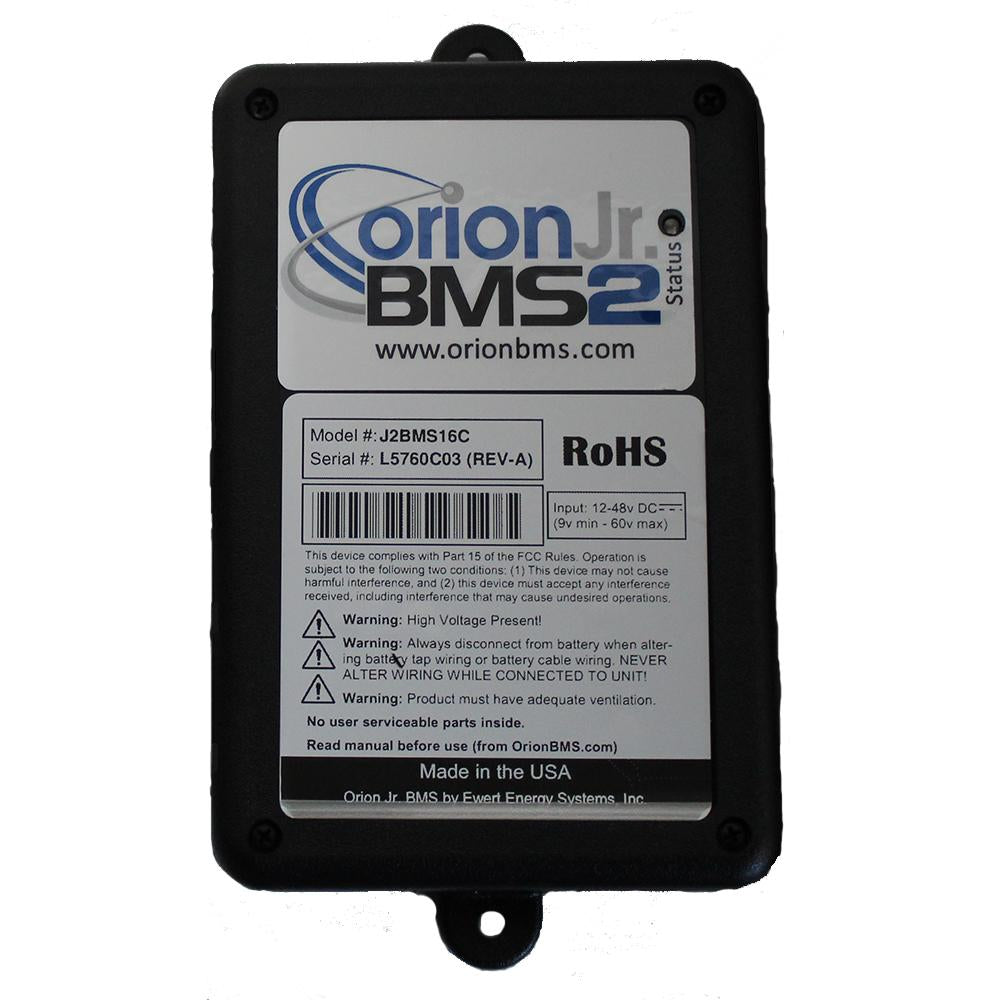
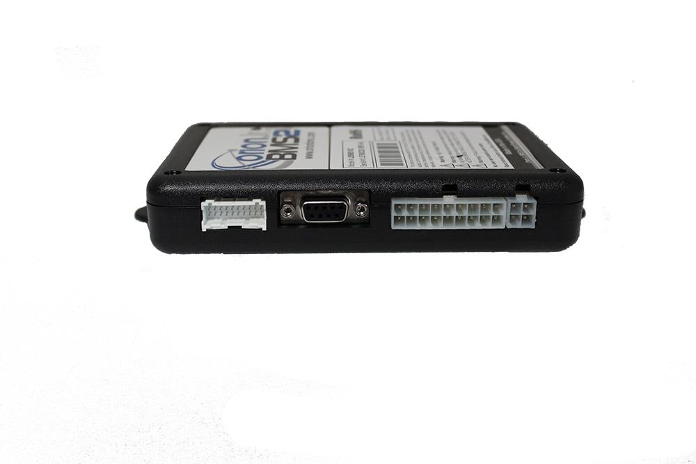
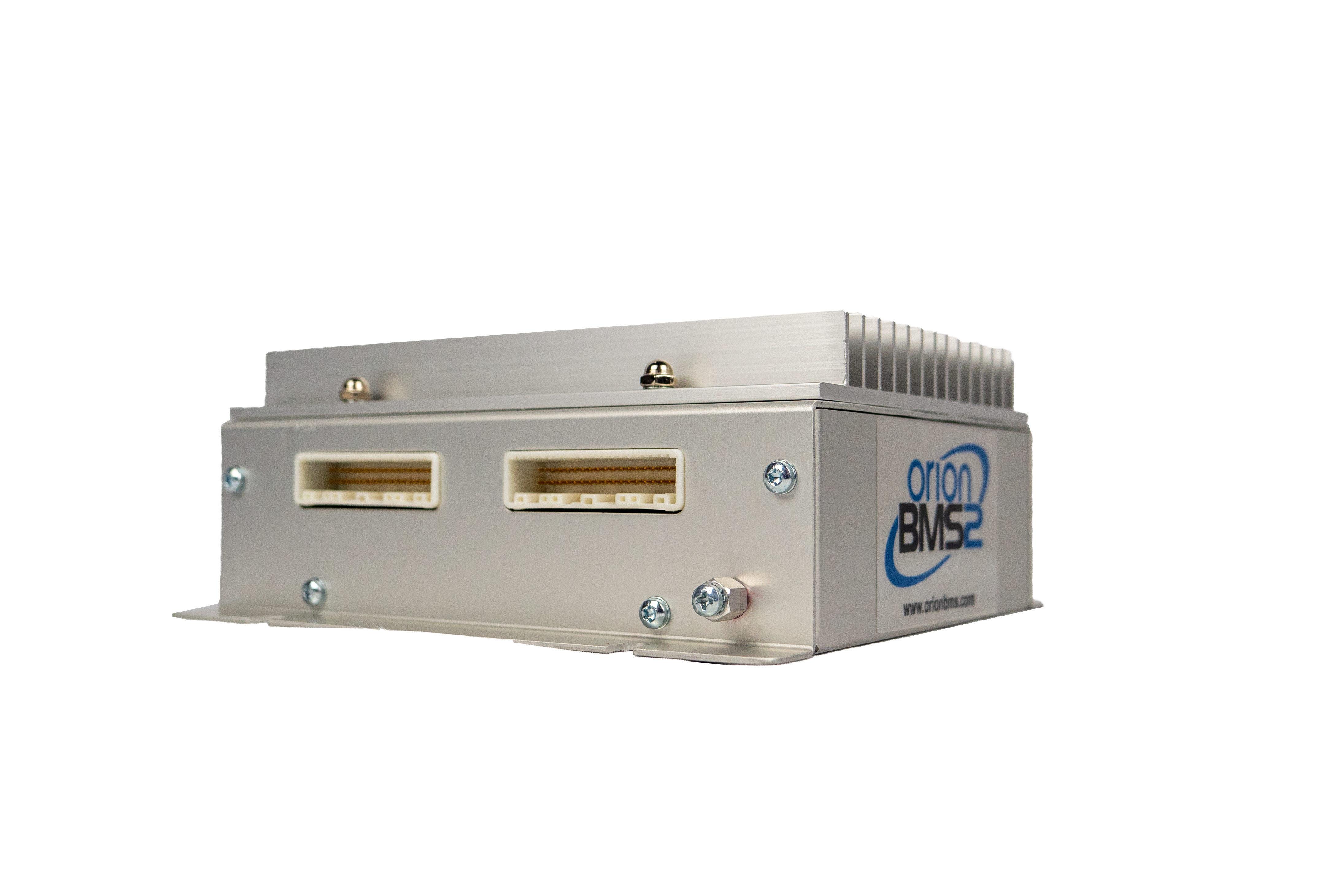
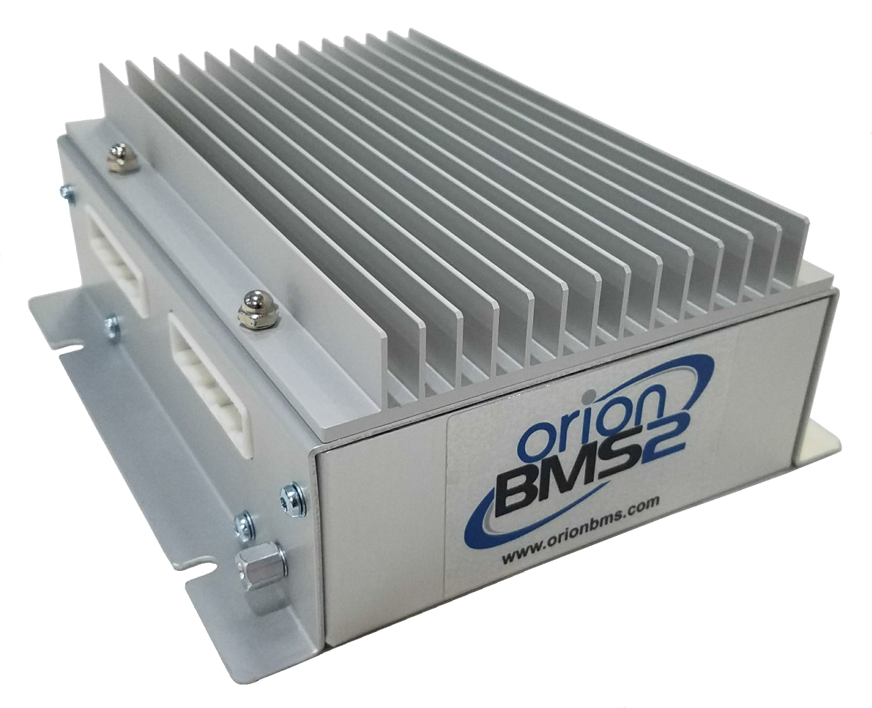
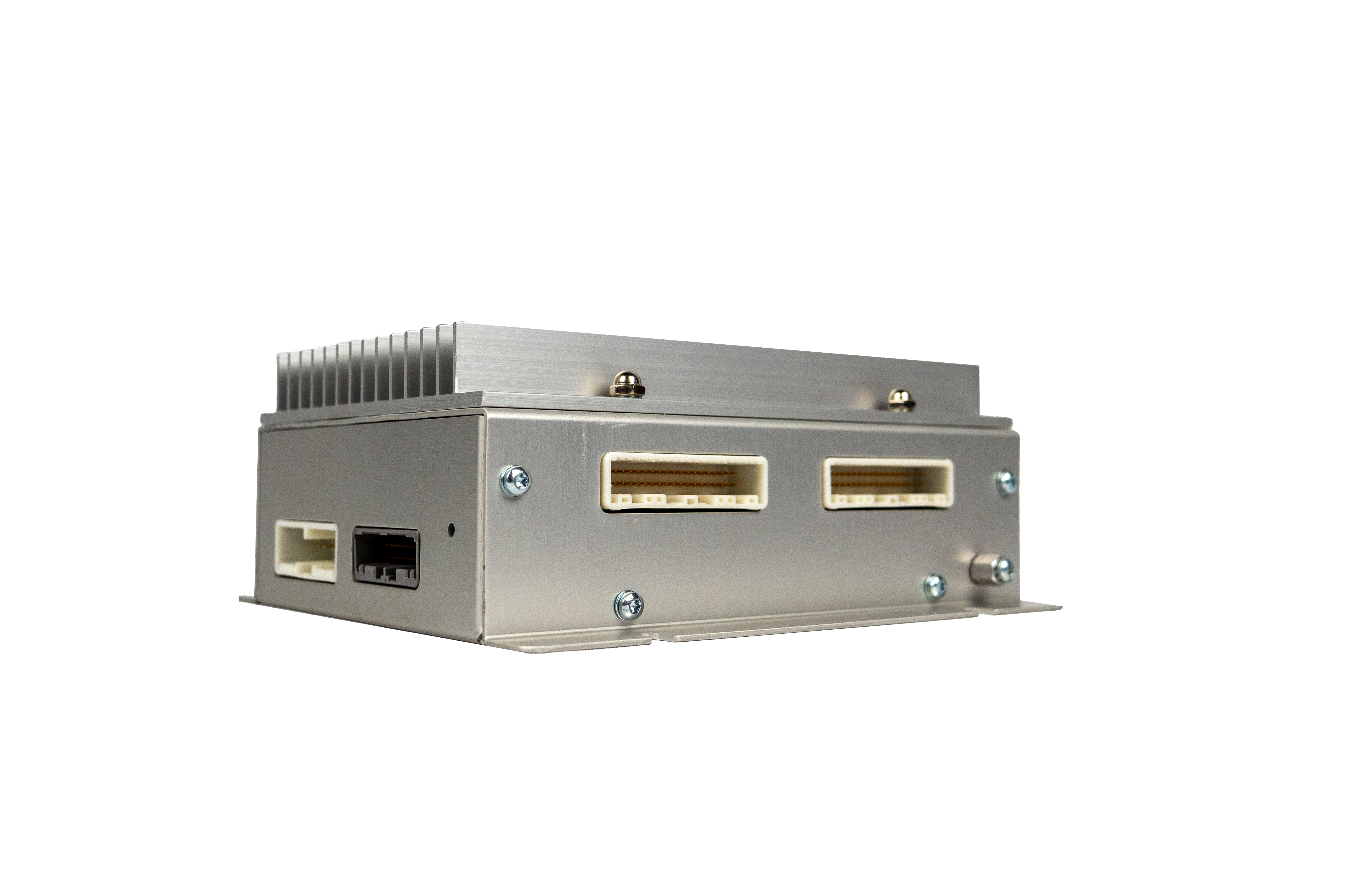
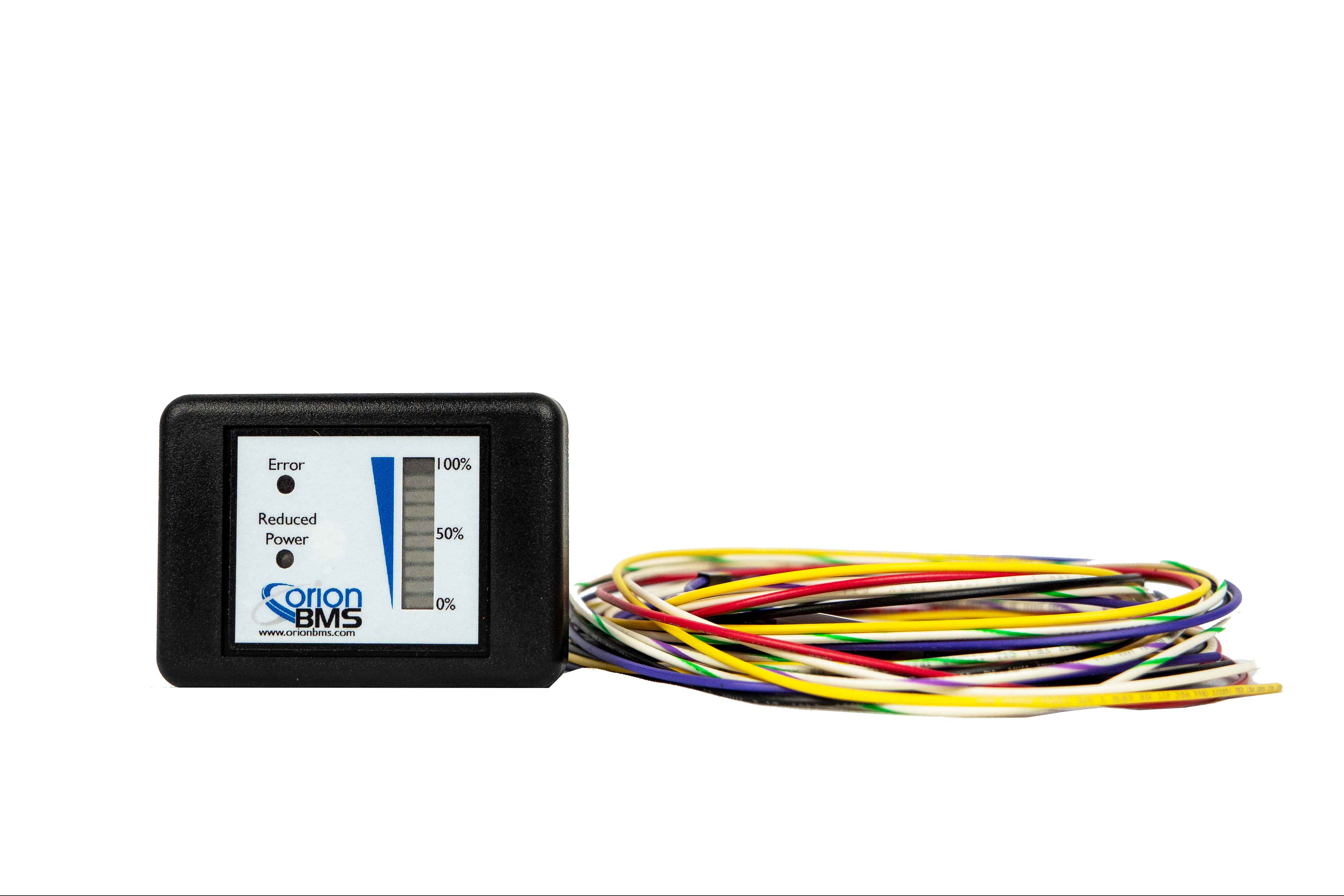
Orion O2 Battery Management System
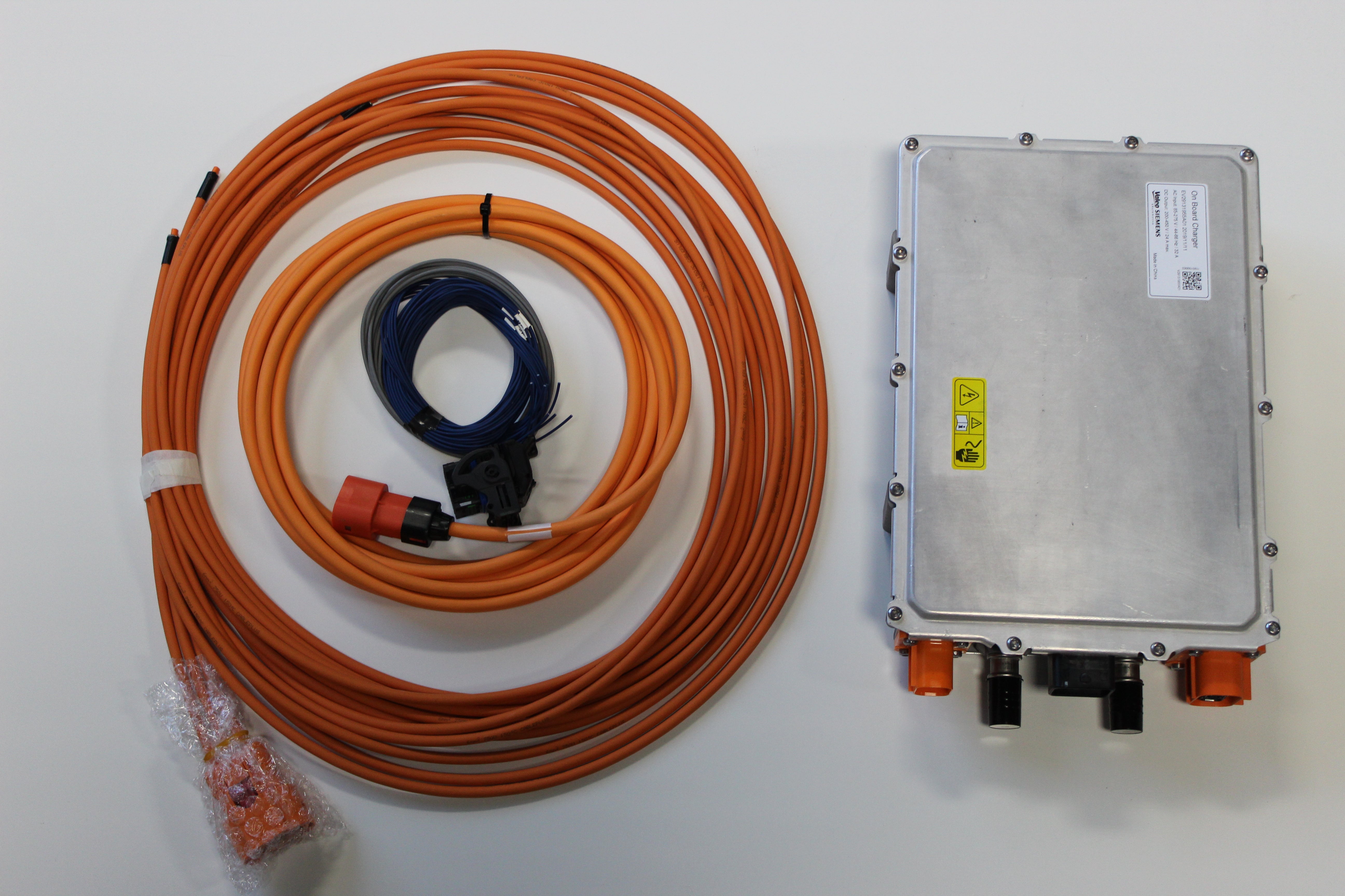
![[Chargers] - EVolve Electrics](http://evolveelectrics.com/cdn/shop/products/Valeo_Siemens_OBC_power_charger_720x_0766ef4a-353a-4059-bfa9-3b1ba01bfac1.jpg?v=1708993136&width=720)
Best Sellers
Orion O2 Battery Management System

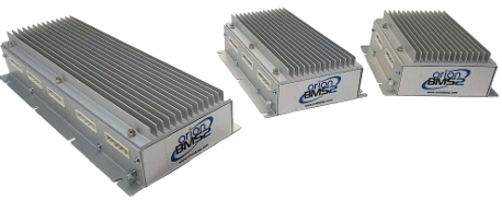

Orion O2 Expandable Battery Management System - BXL


Orion O2 Remote Battery Management System - REM
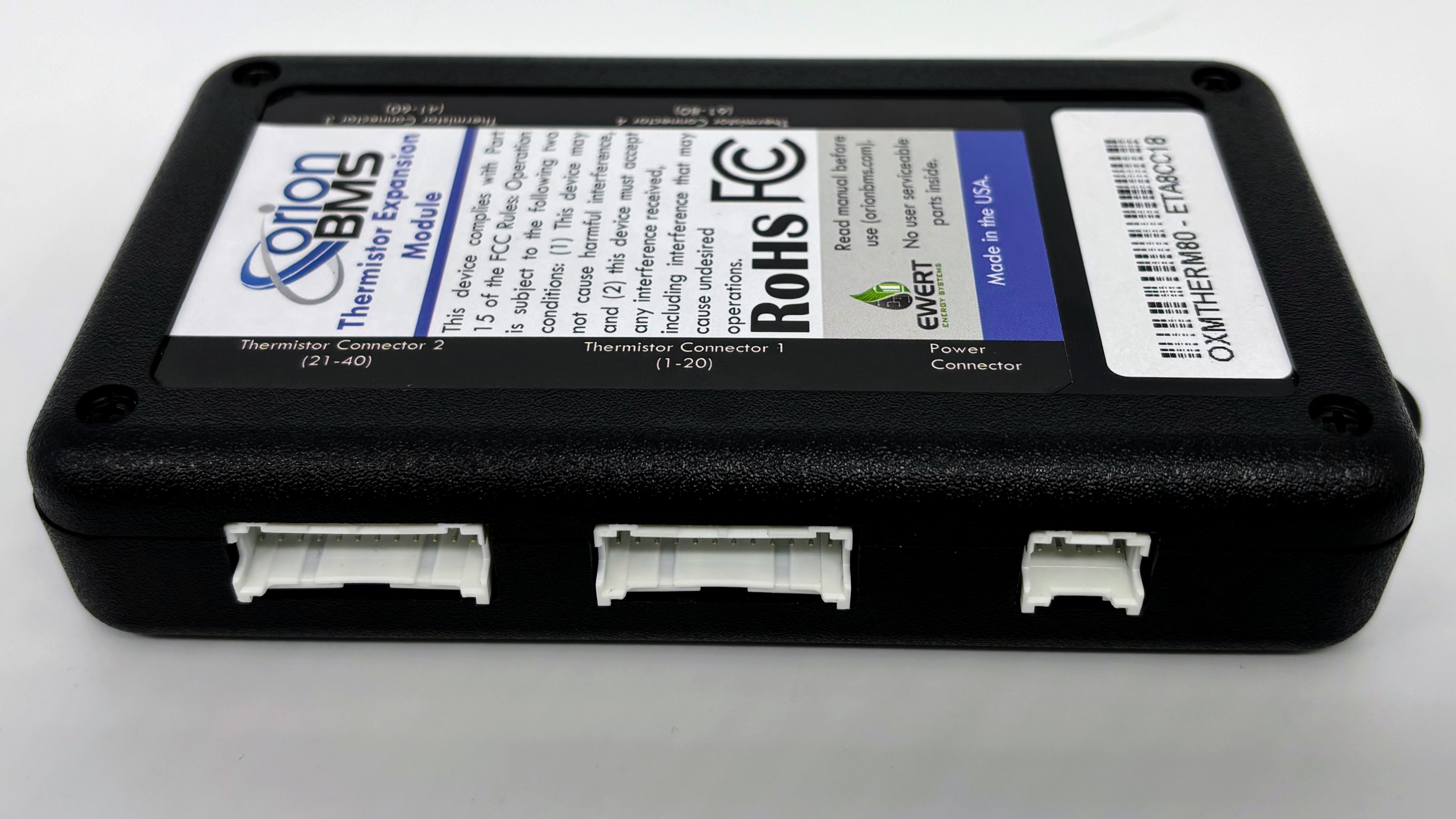
Orion Thermistor Expansion Module
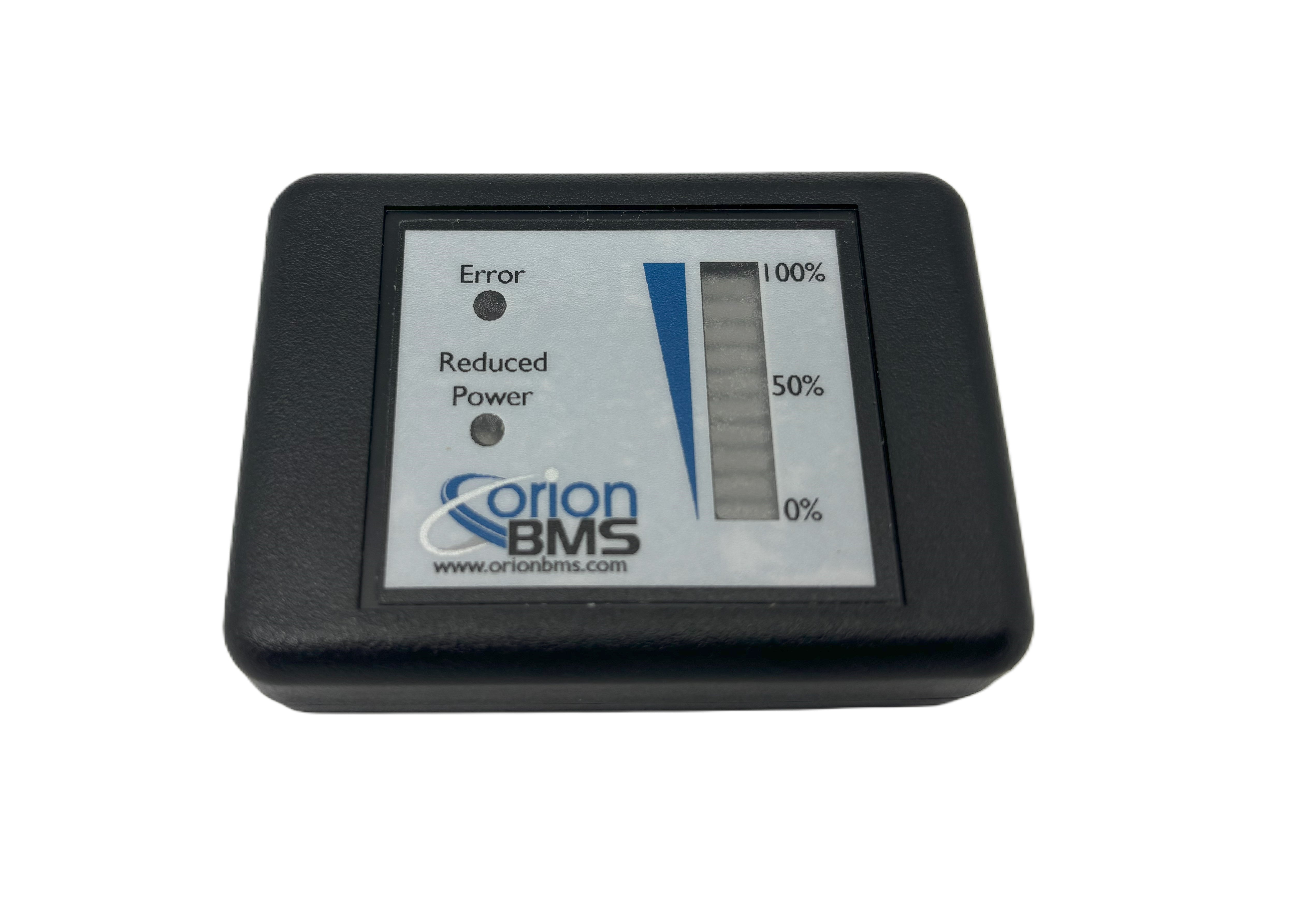
Orion O2 Battery Management System

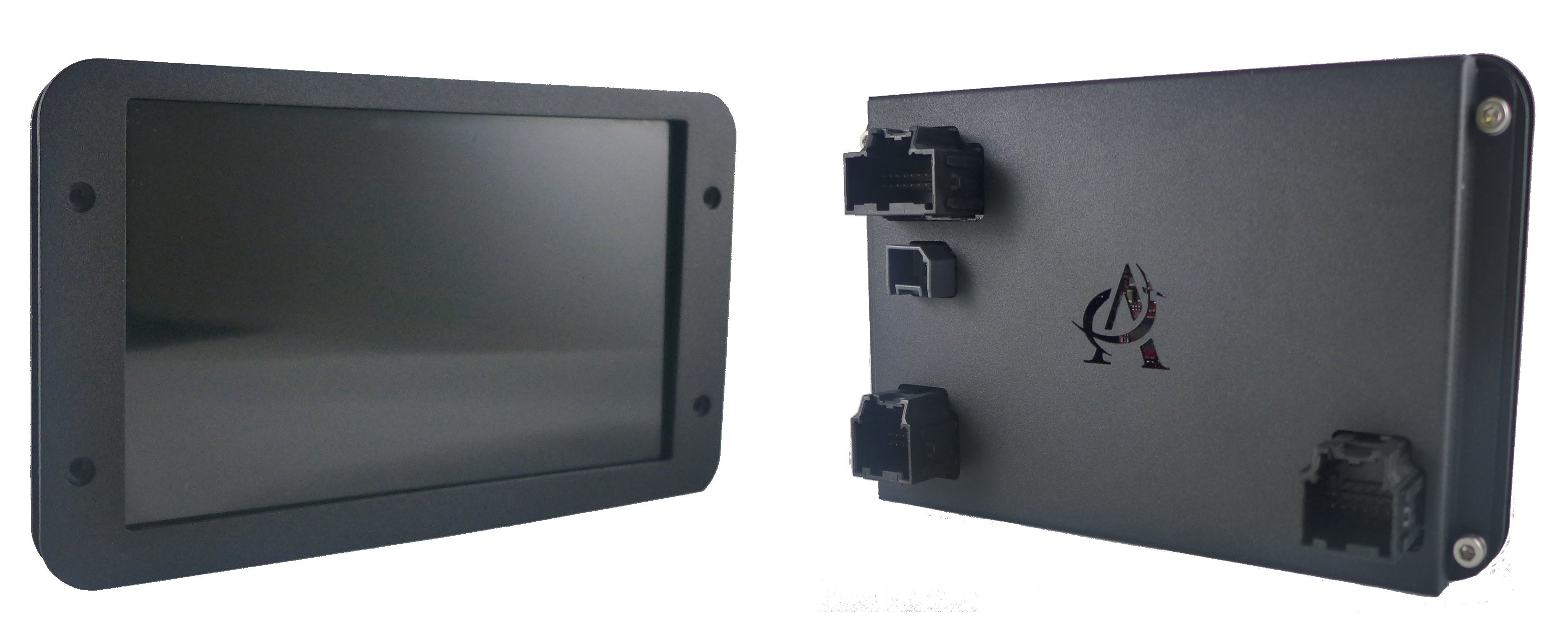
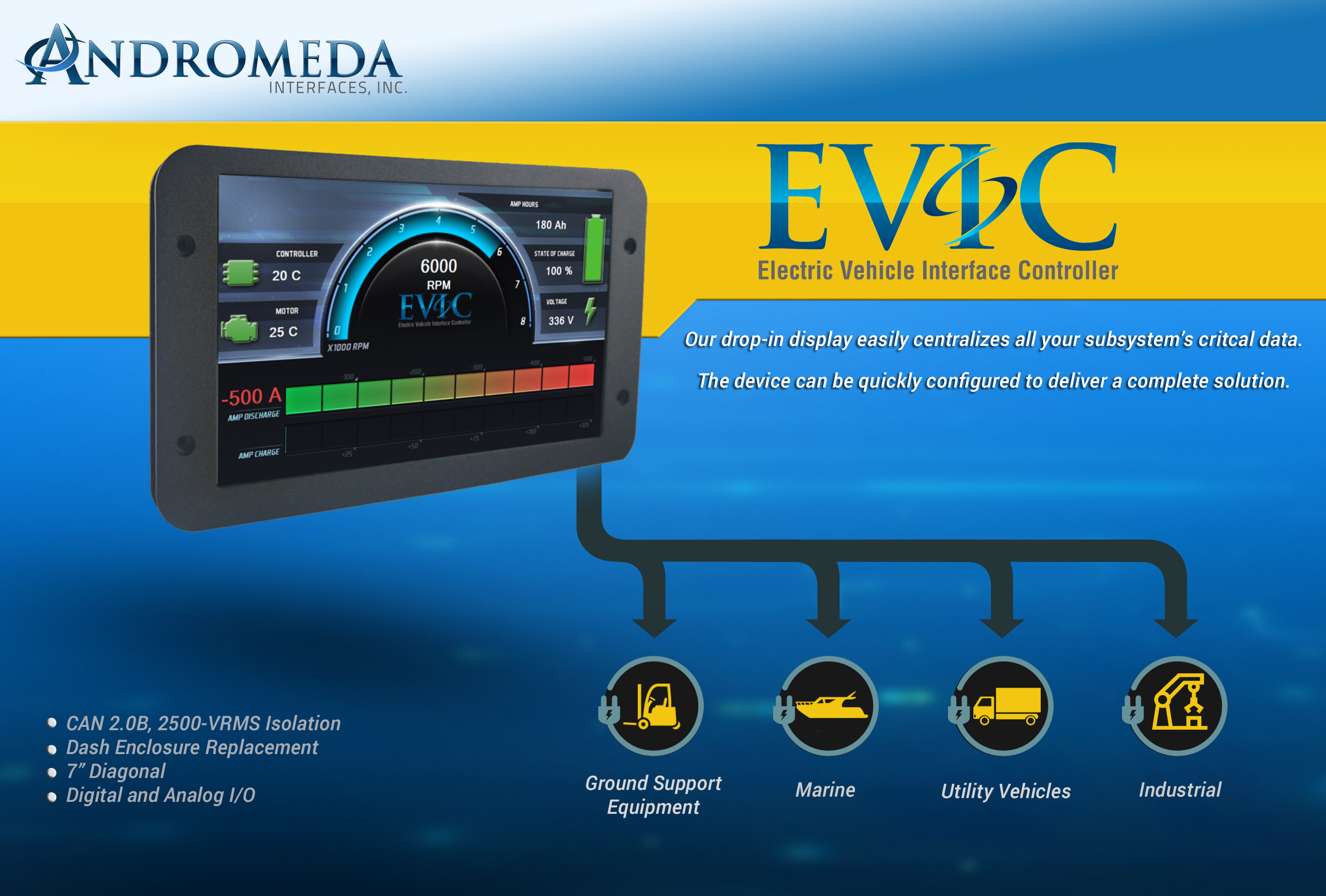
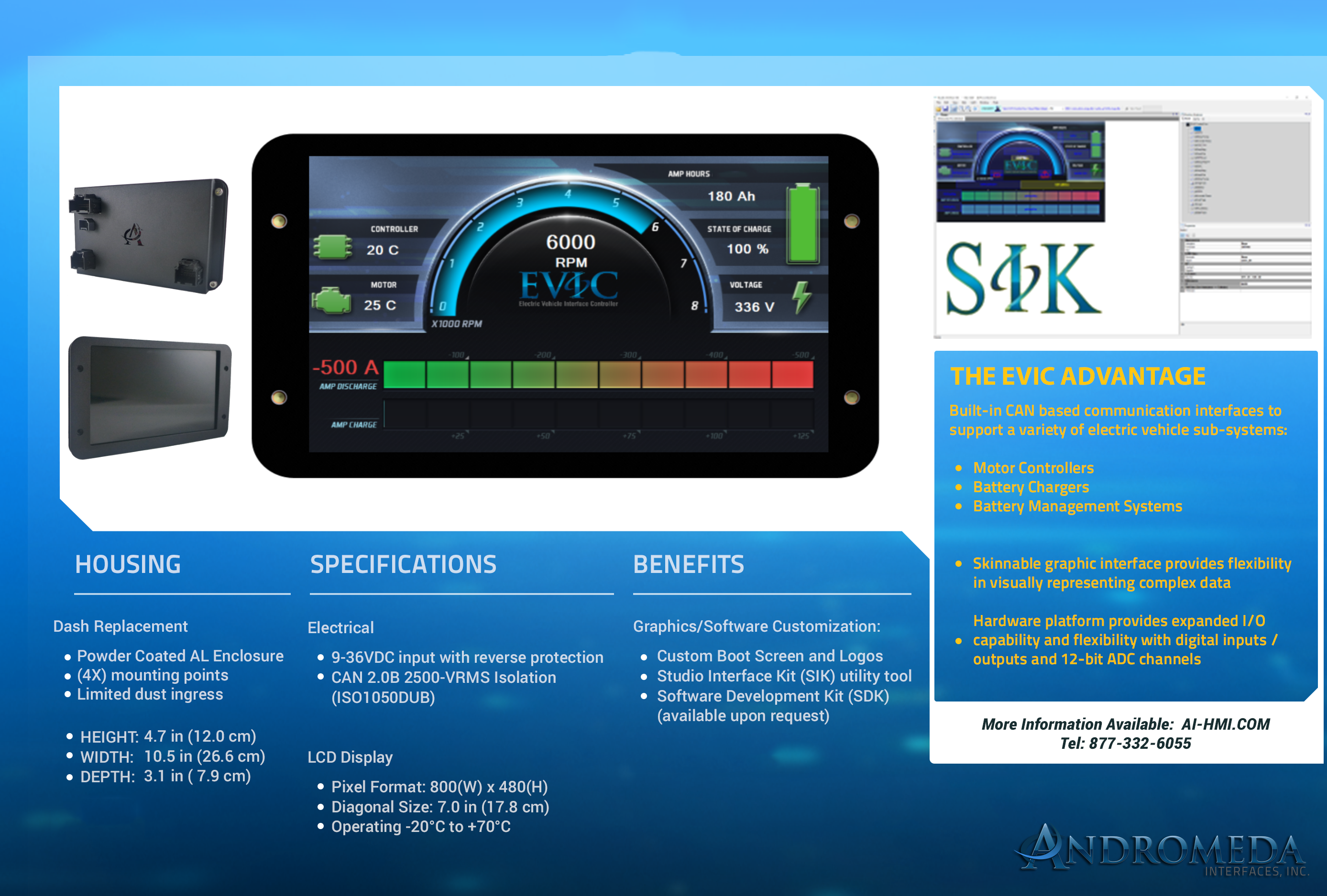
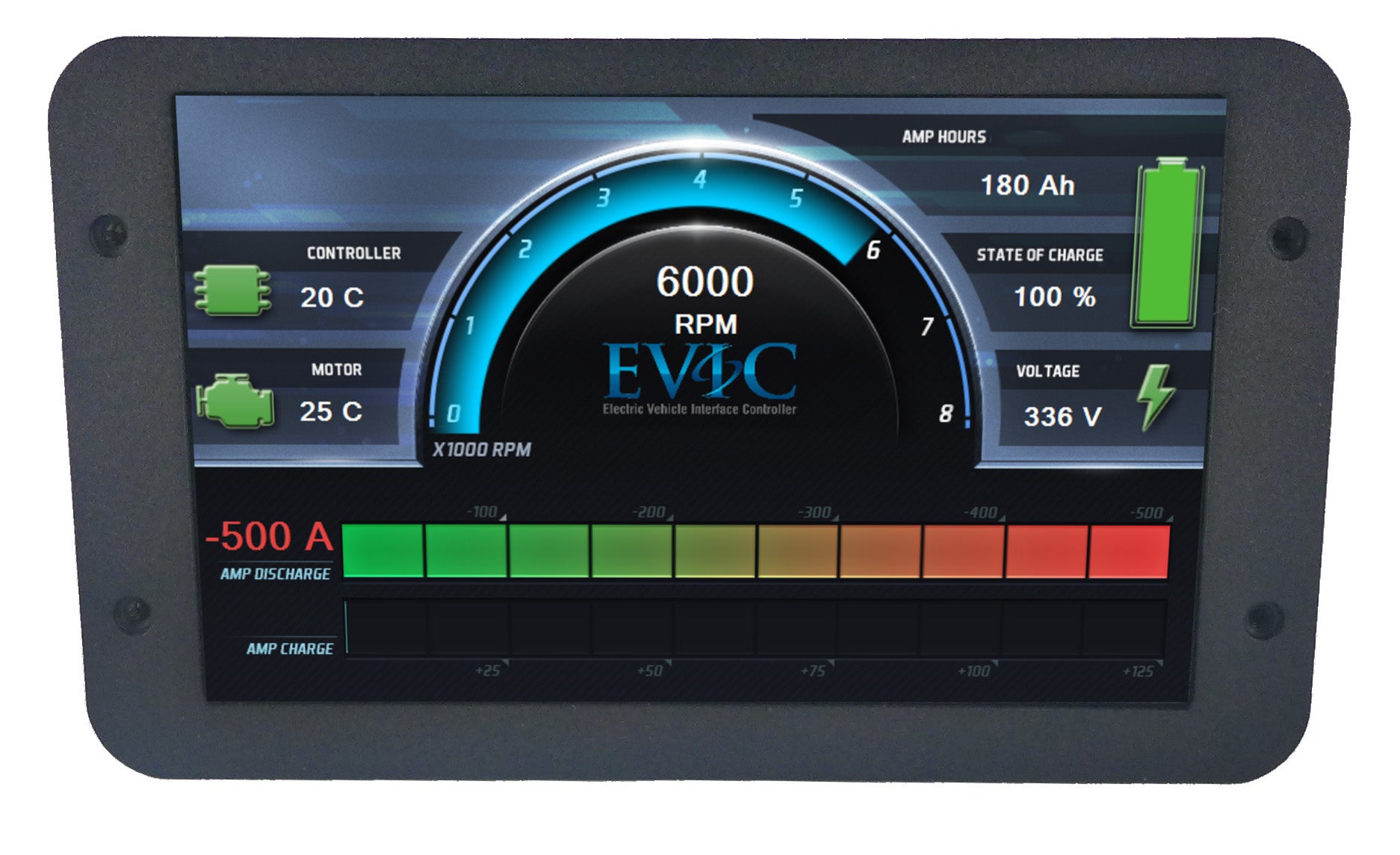
Andromeda EVIC Display & Harness
Orion O2 Expandable Battery Management System - BXL