Andromeda EVIC Display & Harness
Andromeda EVIC Display
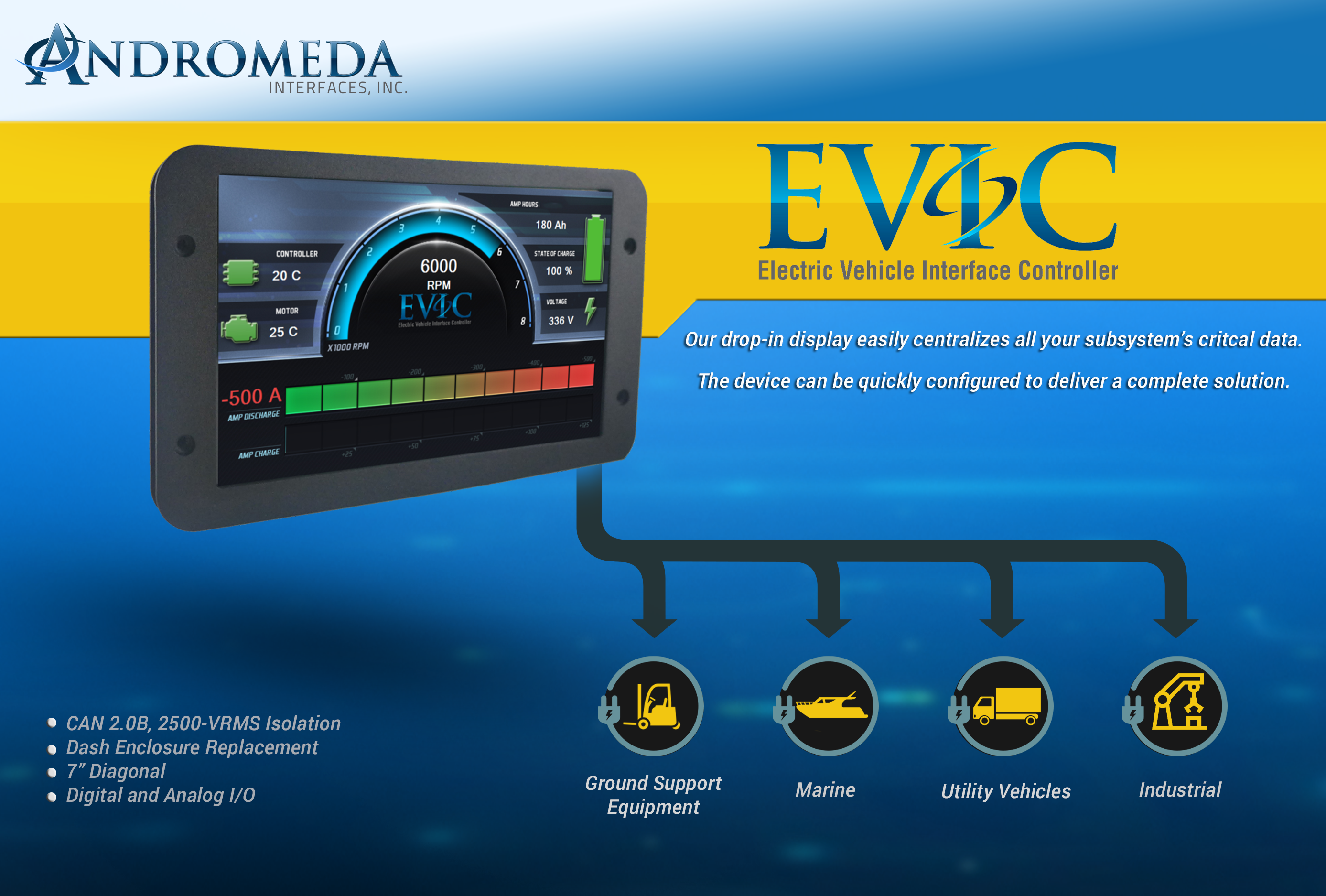
Rugged 7" Color CAN HMI for EV & Industrial Systems
The Andromeda EVIC is a compact, rugged LCD display with an integrated isolated CAN channel, digital and analog I/O, and a flexible software environment. It’s designed to sit at the center of your vehicle or pack interface, streaming live data from battery management systems, motor controllers, chargers, and vehicle control units.
Ideal for EVs, off-highway vehicles, motorsport, industrial equipment, and any application that needs a clean, configurable HMI on a CAN 2.0B network.
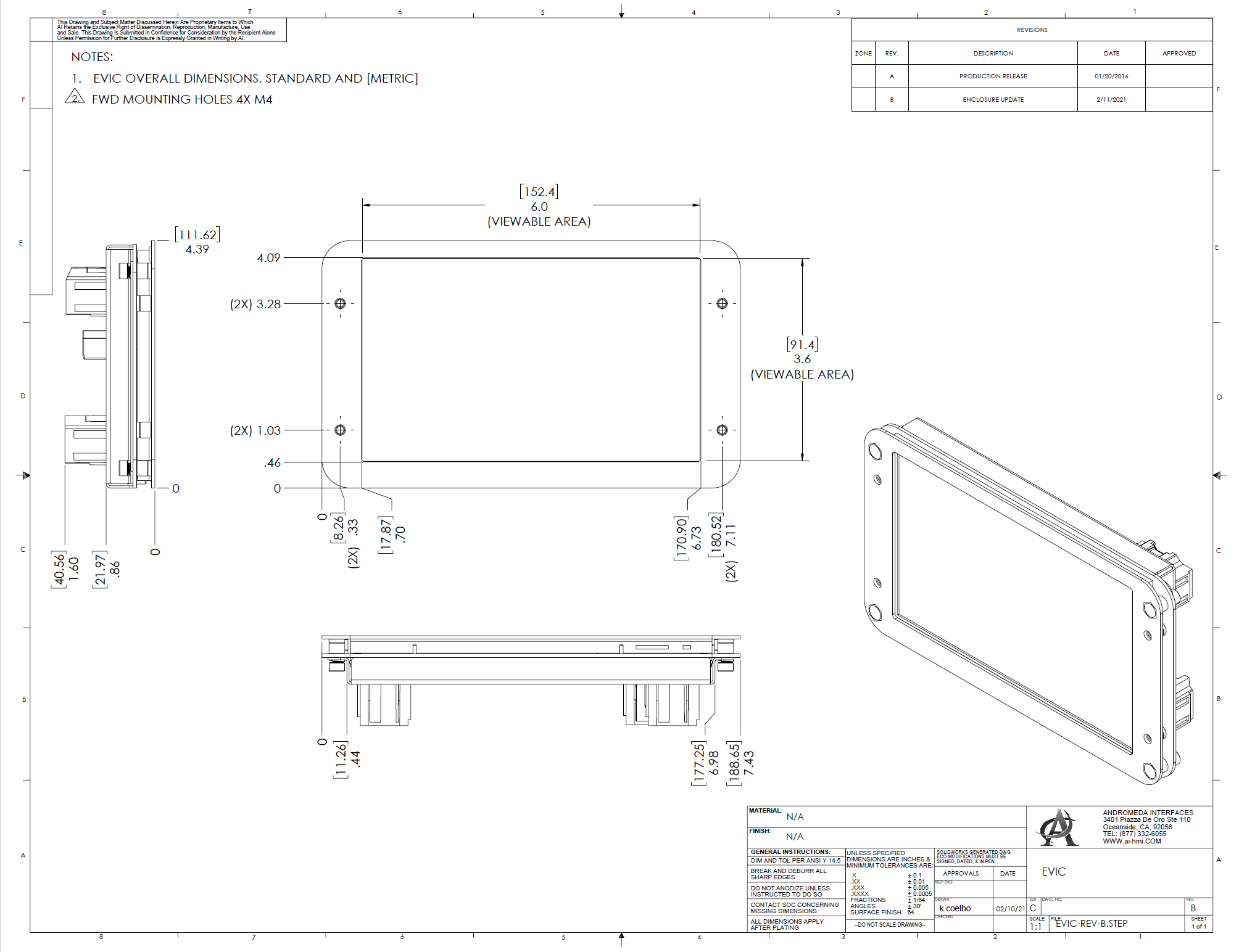
Mechanical & CAD Downloads
Use these files for enclosure design, mounting, and packaging studies.
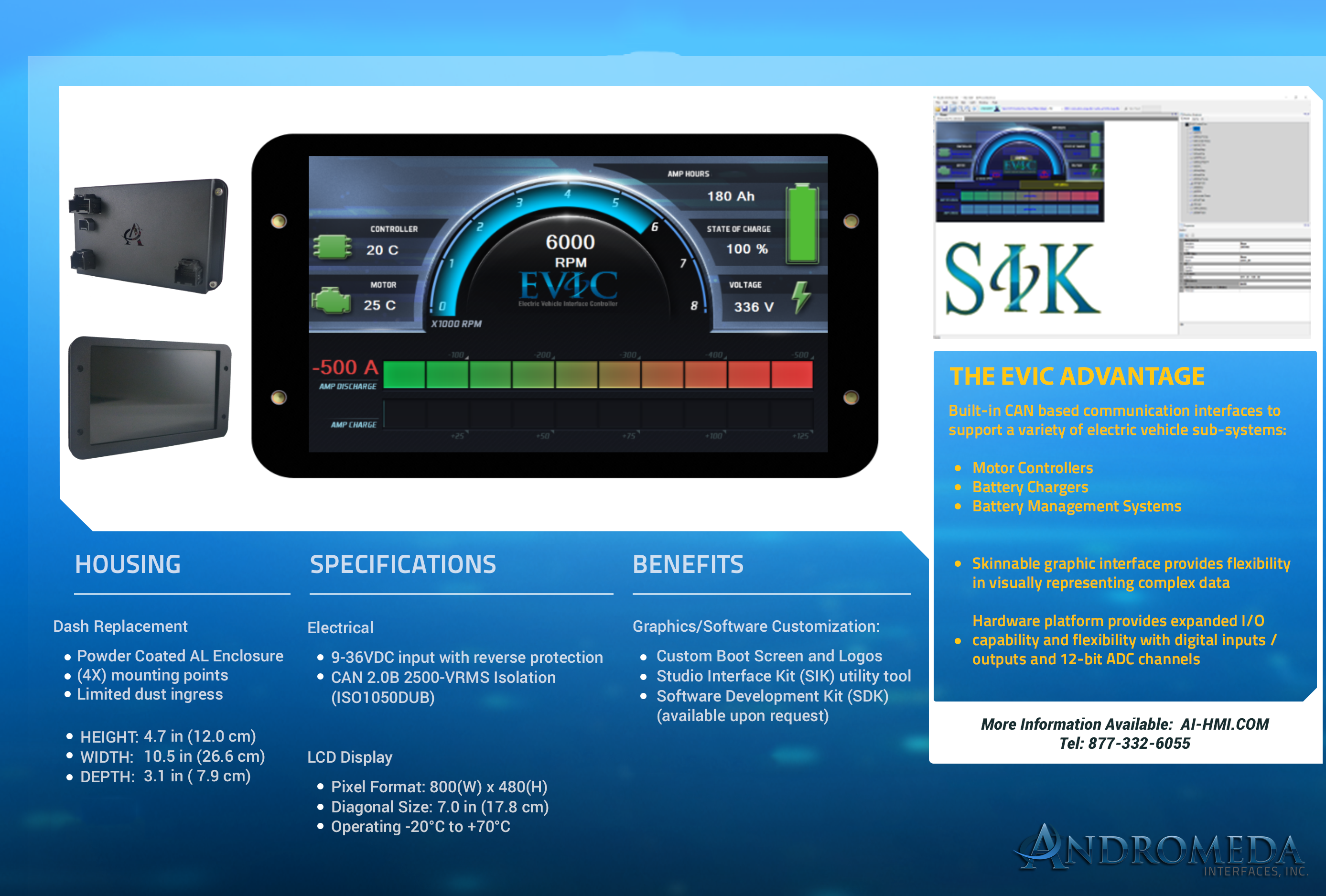
Features & Capabilities
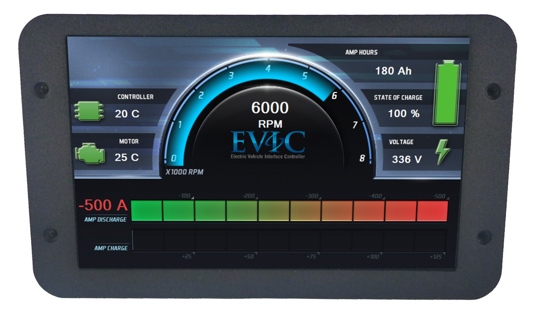
EVIC is designed as a flexible, drop-in HMI for CAN-based systems. It can be configured to show data from battery management systems, motor controllers, on-board chargers, and vehicle control units using configurable screen “skins” and layouts.
Display & Graphics
- 7.0" diagonal TFT LCD, 800 × 480 WVGA
- Active area: 152.4 mm (H) × 91.4 mm (V)
- 16-bit color depth
- Typical brightness: 300 nits
- Supports custom boot screen logos and skin graphics
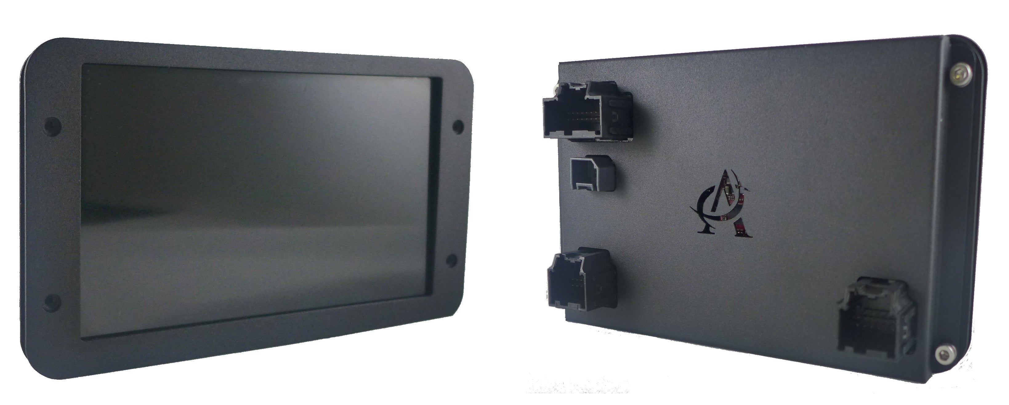
I/O & Connectivity
- 1 × CAN 2.0B channel
- Configurable CAN baud: 125, 250, 500 kbps, 1 Mbps
- 2.5 kV RMS CAN isolation (ISO1050DUB)
- 8 × 18 V tolerant digital inputs
- 8 × low-side switching outputs (up to 2 A each)
- 5 × 0–5 V analog inputs, 12-bit resolution
Software & Customization
- Studio Interface Kit (SIK) software for creating and updating HMI screen graphics
- Software Development Kit (SDK) available on request for deeper customization and application programming
- Supports tailored layouts for EV dashboards, pack diagnostics, and service menus
Electrical Specifications
Operating
| Working Voltage Limits | 9 – 36 VDC |
| Input Protection | Input protected against reverse supply connection. Nominal current draw approx. 300 mA @ 12 VDC. |
Output & EMC Protection
| Reverse Polarity | Designed to meet SAE J1455 (2006) |
| Inductive Switching | Designed to meet SAE J1113-11 (2006), Test Pulse 1 |
| ESD | Designed to meet SAE J1113-13 (2004), powered and non-powered |
Interfaces
CAN Interface
| Protocol | CAN 2.0B |
| Isolation | 2.5 kV RMS (ISO1050DUB) |
| Baud Rates | 125, 250, 500 kbps, 1 Mbps |
Digital Interfaces
| Inputs | 18 V tolerant digital inputs, ×8 |
| Outputs | Low-side switching outputs up to 2 A, ×8 |
Analog Interfaces
| Inputs | 0–5 V analog inputs, 12-bit resolution, ×5 |
Mechanical & Environmental
Operating Environment
| Operating Temperature | −20 °C to +70 °C |
| Non-Operating Temperature | −30 °C to +80 °C |
| Humidity | 95% (non-condensing) at 40 °C; 2% at 40 °C |
| Ingress Protection | IP54 |
Performance & Mass
| Vibration (Random) | Designed to meet SAE J1211 standards |
| Shock | Designed to meet SAE J1211 standards |
| Weight | 1.4 kg |
Typical Applications
- EV pack and powertrain dashboards
- Off-highway and industrial vehicle HMIs
- Battery pack test stands and diagnostic stations
- Motorsport and prototype vehicle instrumentation
- Charger / DC-DC converter status and control displays
Couldn't load pickup availability
Pickup available at EVolve Electrics Office
Usually ready in 24 hoursPairs well with
Andromeda EVIC Display & Harness
If you have any questions, you are always welcome to contact us. We'll get back to you as soon as possible, within 24 hours on weekdays.
-
Shipping Information
Use this text to answer questions in as much detail as possible for your customers.
-
Customer Support
Use this text to answer questions in as much detail as possible for your customers.
-
FAQ’s
Use this text to answer questions in as much detail as possible for your customers.
-
Contact Us
Use this text to answer questions in as much detail as possible for your customers.